TV Zapper Projects
Fixing old televisions is a rewarding hobby that can lead to some interesting projects. This page was inspired by a certain pawn shop owner who asked me if it was possible to create a tazer from TV parts.
DANGER! High Voltage
- This experience writeup is for information purposes only.
- Keep in mind High voltage Precautions like these.
- High voltage may produce copious quantities of ozone, a strong oxidant, which may be harmful to eyes and lungs. Not surprisingly, it also kills bacteria.
- Old, damaged electronics may cause strong odors and even physical illness. Let us clean and repair, or do it yourself with this handy guide.
- There is some danger of inhaling lead fumes if desoldering lead solder. Assume all scavenged parts contain lead. Use only lead free solder, if possible
- Some parts, especially batteries, tubes and lighting, contain lead, mercury or mercury vapor, lithium, cadmium and other harmful elements. Handle with care.
- Some older transformers contain PCB's and other cancer-causing chemicals.
- Old electronics is a dirt, bug and bacteria collector. Electronic parts have sharp edges. Wash everything, including clothing, and wear gloves.
Low-cost spark generator!
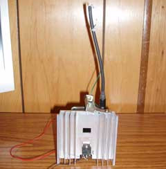
Zapper scavenged from old TV
We pried the cover off and removed the circuit board right where it sat. Lifting the heavy tube and cabinet and transporting it back to the shop woud have been out of the question.
Electronics Recycling
One thing to keep in mind when messing with old TVs is that the internal capacitors must be discharged. These things can carry a lethal electrical charge weeks, months, even years after being unplugged. Discharging them simply requires shorting the hot lead on the tube with an insulated screwdriver or other heavily insulated tool. We used to repair old televisions, but these days it's hardly worth it. Just pry the boards out and salvage.
Fix obsolete TVs with this weird old trick
Surprisingly, it does no harm to an old tube TV to unplug it and pressure wash the interior to remove loose dirt, broken glass and contaminants. Again, make sure the TV is not plugged in! A few drops of dish soap helps to clean the components. Further cleaning with a spray of hot water or a brush may be done as well.
Electronic Recycling
Use wire cutters to remove desired parts and dry on paper towels for several hours. Let dry for at least 24 hours and coat the component leads and solder traces with a light oil mist, such as WD-40, to prevent corrosion.
Flyback Transformers
To remove large parts, like the flyback transformer, carefully go around it with a solder sucker. Breaking the circuit board around the part with needle nosed pliers or a hammer also works. Wear gloves and eye protection. The flyback is the main component in the zapper project. Be careful when handling this as the hot wire (big, heavy wire going into the top of the picture tube) can carry a lethal charge for quite some time. Use a plastic-handled screwdriver wrapped several times with a grounded wire to discharge first. Carefully pry up the rubber boot where it attaches to the picture tube and short the wire inside to ground. The circuit board can then be safely busted out or otherwise removed. Once the boards are out, feel free to use the rest of the machine for target practice.
Horizontal Output Transistors
The HOT can be quickly found by looking near the flyback transformer. It's usually the largest transistor on the board. It will have 3 leads coming out of it marked B, C and E and it will usually be attached to the chassis or a large heat sink. Most sets have an additional HOT or power transistor in the power supply as part of a multi-voltage transformer for the tube heaters, tuner logic and stuff. PNP transistors may also work, with some modification. It will be necessary to reverse the connections around and play with the circuit a bit. Half the fun is in experimentation!
Most TVs are just thrown away because the owners bought a new one and nobody wants to buy their dusty old set. Trash bins are a surprisingly good source of working sets. If they really don't work, however, it's usually because of a bad HOT. One thing people don't realize is that these can usually be substituted with parts from other TVs. As long as the specs are somewhat similar. There is a good chance of combining two non-working sets into one that works. If not, they are usually not worth fixing, new sets being as cheap as they are today, but they can always be parted out!
How to spot a bad HOT
This is fairly easy. Take a volt meter and measure the ohms across the various terminals, B to C, C to B, B to E and E to B. If it reads 0 ohms it's shorted (bad). If there is no reading either direction it's an open circuit (also bad). If it's a higher reading one way than the other it's probably good. Further testing can be achieved by building or buying a transistor tester, or hooking it up in a circuit, such as the zapper, which we have used to test transistors. Comparing readings with a known good component works just as well.
Resistors
For resistors choose something over 1/2 watt, if possible. The values aren't too critical. Swapping 27 and 240 ohm resistors with an 18 and 180ohm is OK. Just try to keep the ratio about the same as it forms a sort of voltage divider network with the battery. Typical horizontal output transistors can handle up to 30 volts without overheating too much. When in doubt, check the transistor specs online. It is necessary to check the resistance of old resistors. They often lie!
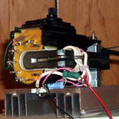
Bottom view
Building the Recycled Zapper
The flyback transformer's internal primary windings may be found by poking around with a volt meter if there isn't a schematic handy. They may be easily bypassed as in the above picture. Just wrap 3 turns of light and 4 turns of heavier wire around the transformer core (pink and white wires in the picture). Use recycled wire and parts clipped from around the circuit boards. The values aren't too critical. Secure the ends with tape so they don't come unwrapped. Solder the parts together like the diagram below. The completed zapper will usually need something to make sparks against so the ground must be found. It is usually the middle terminal on the bottom of the flyback transformer (green wire on the left of the above picture). Try (carefully!) moving the hot wire near the terminals down there and see which one it arcs to the best. The two wires can be taped near each other or mounted on the end of a long wand to make a tazer type of device. With the addition of a homemade capacitor the sparks so generated make a very loud bang (and are probably quite deadly).
Once finished, find parts within the set to mount the heat sink directly to the coil using one or more screws or wire ties. Add batteries and a switch. Here's where a project box or tin can comes in handy.
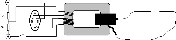
This diagram probably came from here. This is the general circuit we used. Instead of the NPN 2SC3055 power transistor we found that we can substitute just about any NPN horizontal output transistor (also called a HOT) from the TV itself.
The above circuit will perform fairly well since it will fall into an automatic resonance with the coil. Some fine-tuning may help achieve longer sparks, however. A different resistor here, adding or removing a turn there... Some folks recommend cutting the primary winding off old black and white TV flyback cores. These types are probably better for creating a custom voltage multiplier without the built-in voltage multiplication, rectification and extra windings present in color flybacks.
Update 2013: Improved design
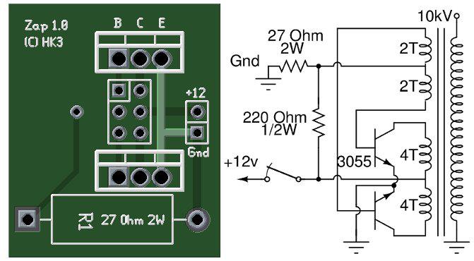
This hasn't been tested, but we found the circuit online, re-routed the traces, and re-drew it from scratch using the free programs, xcircuit and pcb. It's supposed to deliver more power and longer sparks, at the expense of additional battery drain.
 Copyright © 2026 Henry Kroll III, thenerdshow.com This web page is licensed under a Creative Commons Attribution-ShareAlike 3.0 Unported License.